I did decide to redo it for the Teensy 4.1, and I hooked up all 18 inputs:
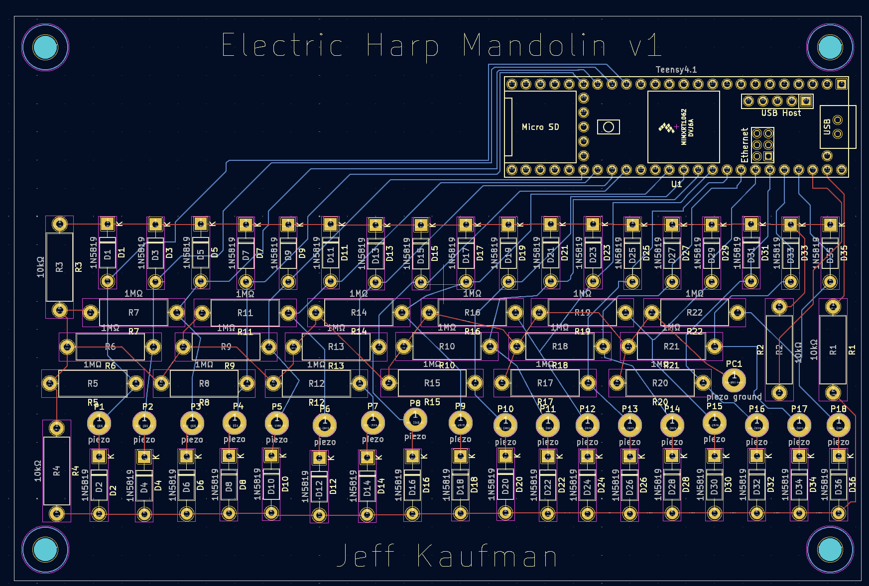
I also added mounting holes, and a bit of writing.
When I did this years ago I used
- EasyEDA, I thought everything else wasn't as easy to use
- PCBway. A ten pack of boards for a nominal fee, the highest cost was shipping.
I got the parts from mouser. Note that if you have a hot air soldering iron and paste it's not difficult to use smd parts of you order the big ones or have a microscope.
Finally I silkscreened the actual values not "r1...rn" and the same for capacitance. This makes hand building easier.
Note that if you have a hot air soldering iron and paste it's not difficult to use smd parts of you order the big ones or have a microscope.
I don't, and haven't used one. I suspect it's not worth getting into it for this project?
I silkscreened the actual values not "r1...rn" and the same for capacitance. This makes hand building easier.
My current draft (as pictured here) does both, which is the KiCad default.
I don't, and haven't used one. I suspect it's not worth getting into it for this project?
The solder paste has a finite shelf life, longer if refrigerated, and the tool is $60-$260 depending on how nice a hot air tool you want. So probably not. When you get deeper in you will hit the issue that almost every modern part is smd with no through hole equivalent. Also it's really neat how you can smear paste on, and the paste thermodynamically wants to stick to metal and connect the part to the pads.
My current draft (as pictured here) does both, which is the KiCad default.
I remembered something. Normally in topology you want to be sure your analog ground, which seems to be piezo ground, is upstream of the digital ground.
Also you seem to be pulling from 3.3 v digital, you may or may not get audible digital interference. Normally you want analog power which comes from a more expensive and specialized power supply different from the supplies that power the digital parts. And topology your analog negative needs to return the that power supply first and then a trace goes to the digital side. This is to reduce noise, you also can do things like a separate internal power plane for each, or to bridge the ground planes at exactly one point between the side for the tiny and the side for the analog circuits. And you would put a bridging component between +5 or +12 and 3.3 that gives analog power linearly.
Example : https://www.analog.com/media/en/news-marketing-collateral/product-highlight/low_dropout_regulators.pdf. (May be massive overkill)
Audio science review forums will have domain experts who are much more knowledgeable than I am about this, it's very hard to make "perfect" analog acoustic circuits where any design compromises are no longer audible. But it can be done.
When you get deeper in you will hit the issue that almost every modern part is smd with no through hole equivalent.
I'm not currently planning to get deeper into this, but we'll see!
Audio science review forums will have domain experts who are much more knowledgeable than I am about this, it's very hard to make "perfect" analog acoustic circuits where any design compromises are no longer audible. But it can be done.
One nice thing about this project is that I'm not trying to capture high-quality audio: I only need it to be good enough to work as a sensor.
Testing with a breadboard the 3.3v digital seems to be good enough, and the noise I'm getting seems to be RF on the piezo lines which is hard to avoid.
A while ago I finished the "user interface" portion of my electronic harp mandolin. I'm happy with the signals the piezos put out, but now I need some electrical engineering to get the signals into a computer where I'll be more at home.
Since I made a design with 13 piezos, I wanted something with at least that many analog to digital converters, and decided on the Teensy 4.0 with 14. It turns out that this only has ten easily accessible ADCs, though, and in retrospect the 4.1 would have been a better choice. More on that later!
Reading the docs, each ADC pin converts an input voltage between 0 and +3.3v into a number between 0 and 1023. The piezo puts out voltages centered on zero, and not guaranteed to have a peak-to-peak of under 3.3v. So we have two problems: how do we bias the pizeo's output up, and how do we ensure it stays in range?
I talked to my TAs and posted on StackExchange, and ended up with this circuit:
To center the pizeo's output halfway between 0 and 3.3v I've used resistors to make a voltage divider. Since R1 through R4 all have the same values, as we go around the circuit each will drop the voltage by the same amount:
To keep voltages from getting too high or low for the ADC I've used two diodes. With an ideal diode this would keep the ADC between +2.48 and -0.83:
Since in practice the diode will have some resistance and some delay, this 2x margin should keep us between 0 and +3.3v.
The R5, in parallel with the piezo, is to pull the ADC pin back to the midpoint.
When running multiple sensors, only the piezo, R5, the diodes, and the ADC pin need to be duplicated; everything else can be shared.
I assembled a single-sensor version on a breadboard, and tested it with a cheap oscilloscope. I'm not totally confident I was using it correctly, but I think it said the voltage was staying within range, so I assembled a two-sensor version and hooked up the microcontroller:
I followed the Teensy tutorial and wrote some code github to look for a pluck and dump the ADC values around it. Here's what I saw:
Looks pretty good! I played with the detection and got it to where it could reliably determine how hard I plucked, and almost always determine which direction. That "almost always" is probably not good enough for a musical instrument, though, so I'll need more work there if I want it bisonoric. Right now it's using that the second peak is nearly always higher than the first, but this isn't quite always true and I think code that looks at the shape of the peaks could help.
I'm also not using the ADC to it's full extent, which is fine for one or two pins but would be a problem when trying to use all of them. There are docs for optimal sampling, but I haven't gone through them yet.
I'd like to move this to a circuit board so I can make something more robust than my breadboard toy, and can include more sensors without driving myself nuts. It looks like KiCad is the standard tool here, and while I normally don't like video for documentation I found this one did a great job with moving fast enough and skipping the repetitive bits. Here's the schematic I ended up with:
If you count the pizeo inputs, why are there only ten? The problem is that only ADC pins A0 through A9 on the Teensy 4.0 are standard pins. The other four ADCs, A10 through A13, are surface mounts on the underside of the board:
The Teensy footprint library I'm using doesn't know about these pins, and I wouldn't want to solder them anyway. Possibly I'll update my design to use a Teensy 4.1, which has pins for A0 through though A17 but for now I just have a ten-piezo design.
KiCad includes a 3D viewer, which is fun, though the library I used for the Teensy apparently doesn't specify a 3D model:
I was thinking of ordering this from JLCPCB, who seem to have very good pricing for low-volume orders?
I think my two main options at this point are to go ahead with this smaller version, or redo it with a Teensy 4.1 to get all the inputs?
If anyone wants to play with the design, the KiCad files are on github.